Hackshroom Chamber — First Flash & Setup Guide
For production chambers with ESP32-WROOM module (UART only).
What you’ll need
Hardware
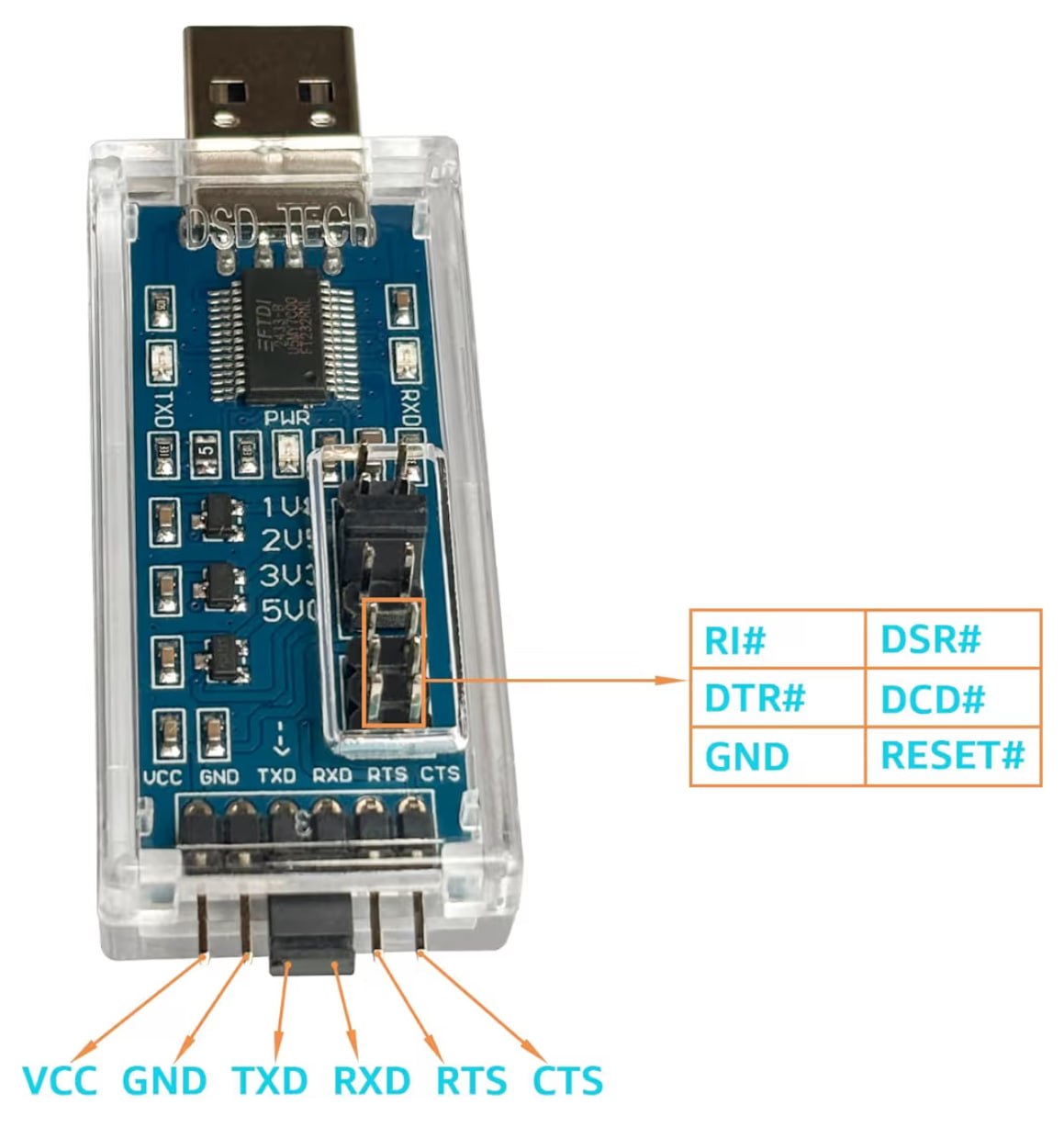
- USB-to-UART adapter: DSD TECH SH-U09C5 (FT232RL, 3.3V logic).
- Jumper wires (at least 5 for flashing control/data).
- Computer (Windows, macOS, or Linux) with Chrome.
Software
- Portable ESPTool (standalone binary from GitHub releases).
- FTDI drivers (usually auto-installed).
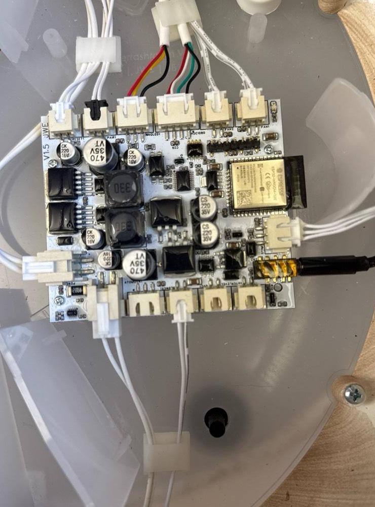
Step 1: Access the internal PCB (disassembly)
Unplug chamber power first. You must remove internal components before cable connectors are accessible.
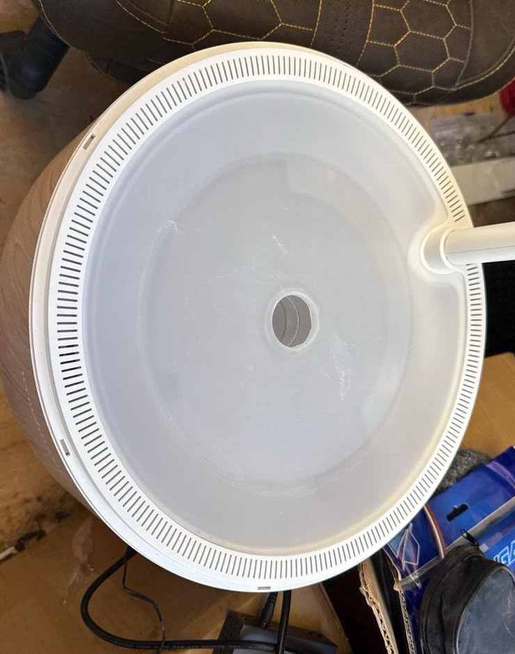
- Remove top plate: lift up and away from the post.
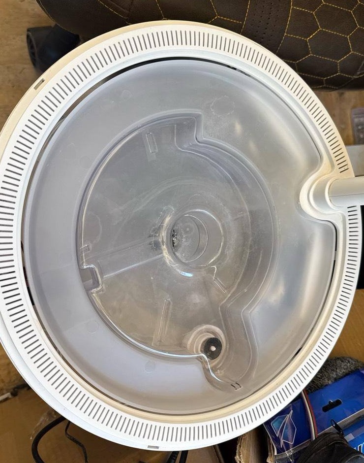
- Remove reservoir: lift from the outer edge/notch, clear center hub, then pull away from wand side.
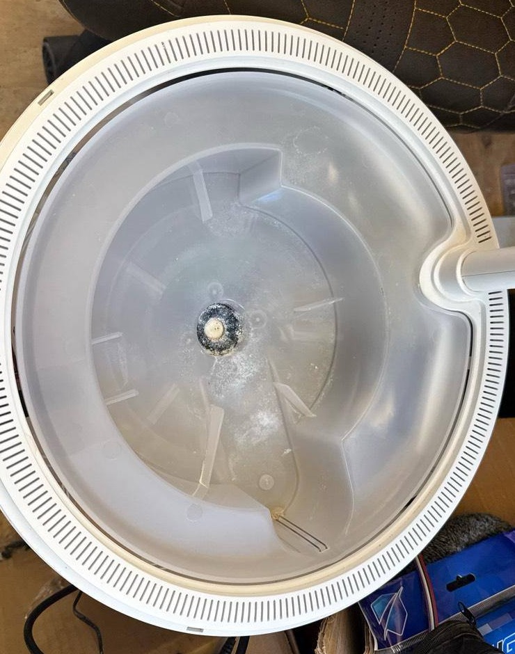
- Remove well base: gently lift and angle assembly out; water-level sensor wiring prevents straight-up removal.
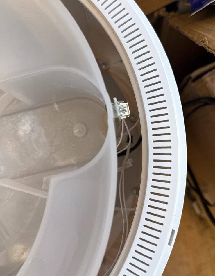
- Watch connector clearance: there is a small connector that can snag while lifting/tilting the well base.
- Before disconnecting anything: take a clear photo of PCB + all connections for reassembly reference.
Step 2: Hardware connection
Critical: set adapter to 3.3V logic. ESP32 is not 5V tolerant.
Do not connect VCC/+5V from adapter if chamber has its own power supply.
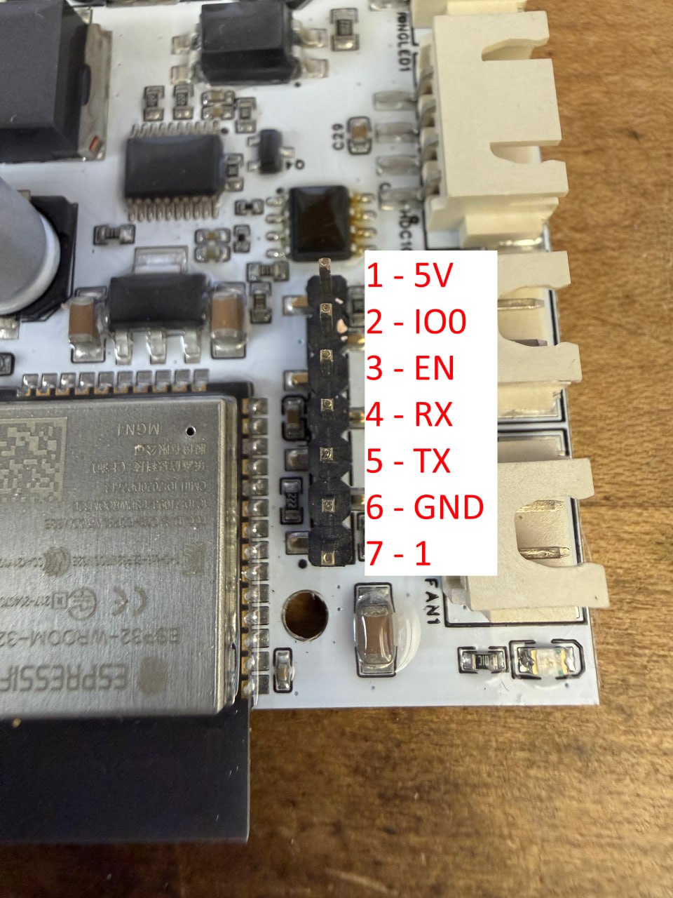
Hackshroom programming header pinout (user-confirmed)
| Header Pin | Board Signal | SH-U09C5 Pin | Notes |
|---|---|---|---|
| Pin 1 | +5V | Not connected | Leave floating for UART flashing. |
| Pin 2 | IO0 | DTR | Boot mode control. |
| Pin 3 | EN | RTS | Reset control. |
| Pin 4 | RX0 | TXD | Crossed UART. |
| Pin 5 | TX0 | RXD | Crossed UART. |
| Pin 6 | GND | GND | Common ground. |
| Pin 7 | 1 | Not connected | Leave unconnected (label as provided). |
- Power off chamber.
- Set SH-U09C5 jumper to 3.3V.
- Connect pins: 6→GND, 5→RXD, 4→TXD, 3→RTS, 2→DTR.
- Leave pins 1 and 7 unconnected.
- Plug adapter into computer and power on chamber.
Step 3: Flash firmware (Portable ESPTool)
Download and setup
- Download standalone ESPTool:
- Extract:
- Windows:
C:\esptool\ - Mac/Linux:
/esptool/
- Windows:
- Place your firmware file in the same folder (example:
hackshroom-1.0.2g-merged.bin).
Find serial port
Windows: Device Manager → Ports (COM & LPT), note COM number.
Mac:
ls /dev/cu.usbserial*Linux:
ls /dev/ttyUSB*Run flash command
Windows:
cd C:\esptool
esptool.exe --chip esp32 --port COM12 --baud 460800 write_flash 0x0 hackshroom-1.0.2g-merged.bin
Mac:
cd /esptool
./esptool --chip esp32 --port /dev/cu.usbserial-XXXX --baud 460800 write_flash 0x0 hackshroom-1.0.2g-merged.bin
Linux:
cd /esptool
./esptool --chip esp32 --port /dev/ttyUSB0 --baud 460800 write_flash 0x0 hackshroom-1.0.2g-merged.bin
If flash fails
- Failed to connect: verify wiring, chamber power, lower baud to 115200.
- Chip not in download mode: re-check EN→RTS and IO0→DTR, then power cycle.
- Hash verification failed: retry at 115200.
- Serial port not found: check drivers/port listing commands.
Step 4: Post-flash setup
- Power off chamber.
- Remove UART wiring.
- Power on chamber normally.
Step 5: First dashboard access
- Look for Wi-Fi SSID
Hackshroom Setup. - When prompted, use password:
growhack. - Connect and complete setup wizard to join your normal Wi-Fi.
- Find chamber IP in router/network scanner.
- Open
http://<chamber-ip>.
Complete initial setup
- Go to Maintenance → Basic Configuration.
- Set timezone.
- Optional Telegram notifications.
- Choose telemetry level: Never / Send Once / Periodic.
Troubleshooting quick hits
- Serial port not found: check FTDI driver + device manager / tty listing.
- Permission denied (Mac/Linux): add user to
dialoutor usesudo. - No setup AP after flash: wait up to 2 minutes, then power cycle.
- No sensor data: wait 60 seconds and check Maintenance logs.
Support
- Reddit support community: r/hackshroom
- Instagram: @masterputterrer
Current firmware version: v1.0.2g · Last updated: April 2026